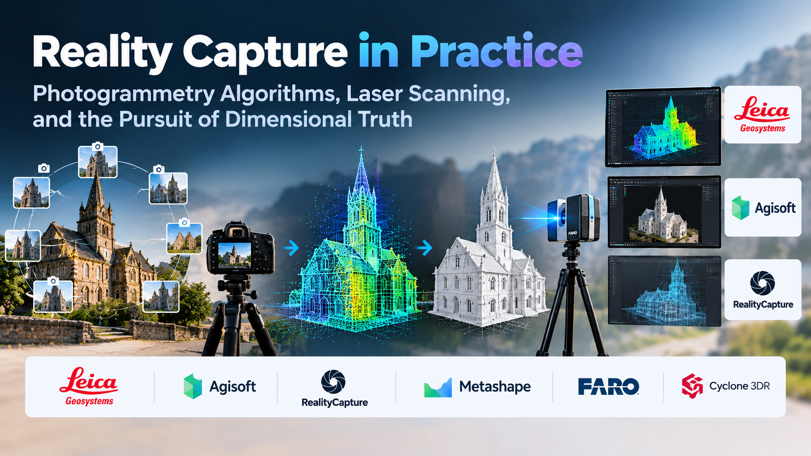
Transforming a physical environment or tangible object into a millimeter-accurate digital replica is often mistaken for a purely optical problem. In reality, modern reality capture is an exercise in applied mathematics, spatial error management, and pipeline trade-offs.
Whether an engineering team is generating as-built Building Information Modeling (BIM) documentation for an industrial plant, an archaeology team is preserving an ancient relief carving, or an environment artist is digitizing rugged cliff faces for a game engine, the core challenge remains the same: how to convert massive, noisy optical or spatial sensor data into structured, topologically valid geometry without losing dimensional truth.
The market conflates several distinct technologies under the catch-all banner of “3D scanning.” A handheld structured-light scanner measuring an aerospace turbine blade operates on completely different principles, error tolerances, and algorithmic architectures than a drone flying an orbital photogrammetry path over an open-pit mine. Selecting the right software platform requires understanding how these disparate spatial streams are aligned, calculated, and transformed into usable assets.
The Three Pillars: Optical Photogrammetry, LiDAR, and Neural Radiance
Reality capture relies on three primary data acquisition and processing methodologies, each with distinct geometric properties and practical constraints.
1. Photogrammetry and Structure from Motion (SfM)
Photogrammetry calculates 3D spatial coordinates by analyzing sets of overlapping 2D digital photographs. It relies on the Structure from Motion (SfM) algorithm, operating through a multi-stage sequential pipeline:
- Feature Detection and Matching: The engine scans adjacent images for high-contrast, identifiable pixels (using algorithms like SIFT or proprietary variants).
- Bundle Adjustment: By tracking how matched features shift relative to camera sensor positions, the software simultaneously solves for camera positions, focal lengths, lens distortion parameters, and the 3D coordinates of the matched points.
- Sparse Point Cloud Generation: A preliminary, low-density cloud of three-dimensional points is plotted in coordinate space.
- Multi-View Stereo (MVS): The software runs dense pixel-matching across images to project depth maps, converting the sparse cloud into a dense point cloud containing millions of spatial coordinates.
- Surface Reconstruction and Texturing: The dense point cloud is triangulated into a polygonal mesh, cleaned, and wrapped in high-resolution diffuse texture maps reprojected from the original camera exposures.
The structural limitation of photogrammetry is its absolute reliance on visual surface texture. Featureless, monochromatic surfaces (like smooth white walls), mirror reflections, transparent glass, and repetitive high-frequency patterns cause feature-matching to fail, resulting in geometric holes, surface warping, and dimensional drift.
2. Laser Scanning: Terrestrial Laser Scanners (TLS) and LiDAR
LiDAR (Light Detection and Ranging) systems bypass optical feature-matching entirely. A laser diode fires pulses of light (often hundreds of thousands per second) toward a surface, and sensitive receivers record the time of flight (ToF) or phase shift required for the beam to return.
Because LiDAR measures physical distances directly rather than inferring them from optical parallax, it operates reliably in total darkness, penetrates thin forest canopies, and captures featureless drywall that defeats optical cameras.
However, raw LiDAR outputs massive, untextured point clouds. Converting these coordinates into clean polygonal surfaces requires intensive registration, noise filtering, and manual or semi-automated meshing. Furthermore, LiDAR systems record intensity values rather than high-fidelity chromatic color; photo-realistic texturing still requires co-registered RGB camera passes.
3. Neural Fields: NeRFs and 3D Gaussian Splatting
A fundamental shift in spatial capture has emerged through volumetric neural representations, primarily Neural Radiance Fields (NeRFs) and 3D Gaussian Splatting (3DGS).
- NeRFs: Train a neural network to approximate a volumetric representation of a scene, mapping spatial coordinates and view angles directly to color and volume density. They produce exceptional view-dependent lighting, capturing real-time reflections and transparency that photogrammetry cannot resolve. However, traditional NeRFs are computationally heavy, slow to train, and difficult to export as standard polygon meshes into downstream CAD, DCC, or GIS tools.
- 3D Gaussian Splatting (3DGS): Bypasses neural network inference entirely by representing scenes as millions of discrete 3D Gaussian primitives (ellipsoids) distributed in space. These Gaussians are rasterized directly to the screen using tile-based compute pipelines, allowing for real-time rendering of complex, semi-transparent environments.
While 3DGS is rapidly transforming visualization, digital twins, and virtual production, it remains a visualization format rather than an explicit geometric representation. For reverse engineering, structural stress analysis, or digital fabrication, explicit mesh boundaries and vector coordinates remain mandatory.
Evaluating the Leading Processing Platforms
The software market for reality capture is sharply bifurcated between geospatial/survey-grade platforms that prioritize geodetic accuracy, and digital media/VFX platforms optimized for polygon throughput, PBR material creation, and mesh extraction.
RealityCapture (Capturing Reality / Epic Games): The High-Throughput Processing Engine
RealityCapture has established itself as an industry benchmark across visual effects, video game development, and high-volume terrestrial surveying.
- Primary Differentiator: Processing speed and dataset scalability. RealityCapture utilizes an out-of-core computing architecture that processes tens of thousands of high-resolution images and massive Terrestrial Laser Scanner (TLS) datasets on standard workstation hardware without memory exhaustion.
- Workflow Strengths: Seamless laser scan and photogrammetry fusion. Users can register raw E57 or PTX laser clouds directly alongside aerial drone imagery and ground-level DSLR photos, combining the dimensional certainty of LiDAR with the chromatic detail of optical cameras. It includes advanced control point management, automated target recognition, and rapid mesh simplification/LOD generation.
- Operational Limitations: RealityCapture’s automated mesh generation creates dense, unstructured triangular meshes that require substantial external retopology, decimation, and UV packing before they can be used in real-time simulation engines or CAD packages.
Agisoft Metashape: The Precision Scientific and Geospatial Authority
Metashape (formerly PhotoScan) remains the primary tool for geologists, aerial mapping technicians, GIS professionals, and cultural heritage documentation specialists who require granular mathematical control over camera calibration.
- Primary Differentiator: Complete transparency in photogrammetric camera parameters and geodetic reference systems. Metashape allows users to inspect and manually adjust internal lens distortion coefficients, principal points, and covariance matrices.
- Workflow Strengths: Exceptional support for multispectral and thermal imagery, specialized drone survey platforms, and broad geodetic datum sets. Its ability to generate precision Digital Elevation Models (DEMs), orthomosaics, and contour profiles makes it a primary asset for land survey, precision agriculture, and volumetric earthwork tracking. It features an open, robust Python API for batch script automation across headless processing nodes.
- Operational Limitations: Dense stereo matching and mesh generation speeds generally trail RealityCapture on equivalent hardware configurations. Its interface is functional and technical, prioritizing data auditing and statistical error reporting over rapid artistic asset preparation.
Meshroom (AliceVision): Open-Source Algorithmic Transparency
Meshroom is a completely free, open-source 3D reconstruction software built on top of the AliceVision computational framework.
- Primary Differentiator: Complete pipeline visibility and zero licensing fees. The software represents the photogrammetry pipeline as an explicit node graph.
- Workflow Strengths: Exceptional educational, research, and non-commercial utility. Because every step—from image feature extraction to depth map filtering and texturing—is represented as an individual node, technical directors and developers can inject custom scripts, change intermediate file formats, or run parallel processes across local networks.
- Operational Limitations: Processing times can be significantly slower than commercially optimized counterparts. The pipeline relies heavily on high-end NVIDIA GPUs with CUDA support, excluding AMD or Apple Silicon configurations from accelerated depth map calculation. Meshroom also lacks the commercial tooling needed to natively align large-scale, registered TLS laser point clouds alongside image sets.
Leica Cyclone 3DR & Register 360: The Terrestrial Metrology Standard
For heavy construction, architectural engineering, plant design, and forensic measurement, software from hardware manufacturers like Leica Geosystems dominates the field.
- Primary Differentiator: Direct hardware integration, target extraction, and rigorous survey reporting.
- Workflow Strengths: Leica’s suite focuses on millimeter-level point cloud registration and verification. Cyclone Register 360 allows surveyors to link multi-station scans via black-and-white planar targets, survey control coordinates, or targetless cloud-to-cloud matching with clear statistical error reports. Cyclone 3DR then translates those point clouds into inspection deliverables: cross-sections, tunnel profile analysis, surface deviation heatmaps against nominal CAD designs, and as-built clash detection.
- Operational Limitations: These platforms are costly, enterprise-tier desktop products with strict licensing constraints. They are designed for engineering compliance, civil infrastructure, and surveyor workflows rather than creative asset production; converting a mesh for a creative game engine or film shot inside Cyclone is cumbersome.
Polycam and KIRI Innovations: The Mobile and Neural Vanguard
Mobile edge capture platforms have evolved from novelty smartphone tools into practical capture suites for quick field reviews, architectural assessments, and e-commerce asset generation.
- Primary Differentiator: Immediate cloud and on-device processing using consumer hardware. Platforms like Polycam use the built-in LiDAR sensors of modern mobile devices for rapid spatial mesh capture, while simultaneously offering cloud photogrammetry and 3D Gaussian Splatting processing for high-resolution photo sets.
- Workflow Strengths: High velocity and minimal equipment friction. A technician or field agent can walk an interior room, capture spatial bounds with onboard LiDAR, generate a dimensionally accurate floor plan, and export directly to CAD formats or web-based 3D viewers in minutes.
- Operational Limitations: Mobile LiDAR has limited effective range (typically under 5 meters) and lower spatial resolution compared to dedicated terrestrial scanners or high-resolution DSLR photogrammetry sets. Cloud-based reconstruction pipelines offer limited access to intermediate parameters, making them less suitable for high-precision metrology or strict data-governance pipelines.
Architectural and Operational Comparison
| Software | Core Processing Engine | Primary Data Inputs | Primary Operational Fit | Key Technical Advantage | Significant Trade-Off |
| RealityCapture | Multi-View Stereo (MVS) + Out-of-Core GPU Engine | RGB Photos, TLS Scans (E57, PTX), Drone RTK/PPK | VFX, game environments, large-scale survey, mixed scan fusion | Rapid processing speeds; simultaneous laser and photo fusion | Unstructured triangulated mesh outputs require external retopology |
| Agisoft Metashape | Photogrammetry + Dense Stereo Reconstruction | RGB, Multispectral, Thermal, Drone Video | GIS, civil mapping, archaeology, scientific measurement | Deep lens calibration auditing, DEM/Orthomosaic generation | Slower baseline compute times than high-velocity commercial engines |
| Meshroom | Open-Source AliceVision Framework | RGB Images (DSLR, Mobile, Action Cam) | Academic research, indie VFX, pipeline experimentation | Node-based workflow; open-source and scriptable; zero cost | Slower dense cloud extraction; requires CUDA-compatible NVIDIA hardware |
| Leica Cyclone 3DR | Point Cloud Metrology & CAD Inspection Engine | Terrestrial Laser Clouds (PTS, E57), Spatial Meshes | Civil infrastructure, plant engineering, BIM, forensics | Direct clash detection, CAD deviation heatmaps, survey audit logs | Expensive enterprise licensing; steep operational focus on survey engineering |
| Polycam | Mobile Sensor Fusion (LiDAR) + Cloud SfM / 3DGS | Mobile LiDAR, Smartphone Photos, Drone Feeds | Field estimation, quick digital twins, rapid web visualization | Immediate capture turnaround; native 3D Gaussian Splatting exports | Low spatial resolution; limited manual control over internal reconstruction parameters |
Critical Factors in Precision and Pipeline Interoperability
The quality of a 3D scan is determined before software processes the first pixel. Understanding the physical and computational constraints prevents costly reconstruction failures.
Ground Sample Distance (GSD) and Optical Sampling Density
In aerial and terrestrial photogrammetry, Ground Sample Distance (GSD) defines the physical distance between two consecutive pixel centers measured on the ground. A GSD of 1 cm/pixel means one pixel in the photograph represents a 1 cm square in the physical world.
If an engineer needs to capture a crack measuring 2 mm in concrete, the GSD must be significantly smaller than the defect itself (typically a third of the feature size or lower). Increasing resolution requires either closer camera proximity, a lens with a longer focal length, or a higher-resolution sensor—each multiplying the total image count and subsequent compute overhead.
Ground Control Points (GCPs) and Geodetic Scale
Unscaled photogrammetry produces visually believable models that have no inherent scale or orientation. The software reconstructs relative spatial relationships, meaning a miniature sculpture could be interpreted as a hundred meters tall.
Establishing absolute dimensional accuracy requires Ground Control Points (GCPs):
- Target Placement: High-contrast, mathematically recognizable targets are placed across the physical scene before scanning.
- Survey Validation: The precise coordinates of these targets are recorded using high-precision total stations or RTK (Real-Time Kinematic) GNSS receivers.
- Constrained Adjustment: During processing, these real-world coordinates pin the sparse point cloud, correcting for common systematic errors such as the “bowl effect” (long-distance photogrammetric drift where flat terrain curls upward due to uncorrected radial lens distortion).
Point Cloud to CAD: The Reverse Engineering Bottleneck
Generating an accurate mesh is only half the battle. Downstream mechanical engineers and architects cannot easily work with a 50-million-polygon raw STL or OBJ file in CAD environments like SolidWorks or Revit.
Converting reality capture into usable CAD requires reverse-engineering pipelines:
- Sectioning: The raw mesh is sliced with coordinate reference planes to extract 2D vector profiles.
- Primitive Extraction: Algorithmic tools fit perfect analytic primitives (planes, cylinders, spheres, cones) to the underlying point cloud clusters.
- Deviation Mapping: The CAD model is compared back against the original point cloud, generating color-coded deviation heatmaps that illustrate whether manufactured parts fall within specified machining tolerances.
Strategic Selection Framework
To select the right reality capture environment without overspending or bottlenecking production, map your team’s practical output requirements across these operational paths:
Path A: The Visual Effects Studio, Game Developer, or 3D Artist
- Primary Need: Converting organic environments, props, and architectural sets into high-resolution visual assets.
- Recommended Platform: RealityCapture.
- Deciding Factor: Throughput and scan fusion. When processing thousands of high-resolution RAW photos alongside terrestrial LiDAR scans, RealityCapture’s out-of-core engine prevents memory crashes and provides fast alignment, allowing concept and environment artists to review photorealistic geometry within hours.
Path B: The Civil Surveyor, Geospatial Analyst, or Field Archaeologist
- Primary Need: Certified dimensional accuracy, geodetic positioning, orthomosaics, and elevation profiles.
- Recommended Platform: Agisoft Metashape.
- Deciding Factor: Scientific auditability. Metashape gives users deep access to camera calibration matrices, georeferencing adjustments, and specialized multispectral drone inputs, making it the preferred choice when deliverables must stand up to rigorous survey inspection.
Path C: The Construction Manager, Plant Engineer, or Metrology Inspector
- Primary Need: As-built verification, clash detection against architectural CAD/BIM models, and structural tolerance inspection.
- Recommended Platform: Leica Cyclone 3DR / Register 360.
- Deciding Factor: Specialized metrology deliverables. These engineering-grade platforms directly extract deviation heatmaps, floor flatness (FF/FL) ratings, and structural deformation profiles from registered point clouds, linking directly into enterprise BIM and facility management workflows.
Path D: The Academic Researcher, Indie Experimenter, or Pipeline Developer
- Primary Need: Open access, zero budget overhead, and algorithmic experimentation.
- Recommended Platform: Meshroom (AliceVision).
- Deciding Factor: Algorithmic transparency. By exposing the mathematical structure of the SfM and MVS process through an open node-based interface, Meshroom provides a deep platform for educational exploration, custom scripting, and automated non-commercial asset conversion.
Validating Reality Capture Software Before Deployment
Before procuring commercial licenses or committing to a capture platform, execute a structured pilot project to test performance under adverse real-world conditions:
- The Featureless Surface Test: Photograph an object containing both high-frequency texture and smooth, monochromatic areas (such as a painted sheet metal enclosure or an interior drywall room with simple lighting). Observe how the software handles the untextured boundaries: does it bridge the gaps cleanly, or does it produce fragmented, corrupted geometry?
- The High-Density Alignment Benchmark: Take a standardized dataset of at least 1,000 high-resolution images. Run the initial feature detection, matching, and bundle adjustment phases. Document total processing time, RAM saturation, and the percentage of images that align without requiring manual tie-point placement.
- The Scaling and Dimensional Tolerance Check: Place an object with known, certified dimensions (measured via calibrated vernier calipers or a metrology gauge block) inside the scanning volume. Process the data without manual scale inputs, then scale the model using placed reference targets. Measure the calculated distance between reference points against the physical gauge to verify dimensional drift.
- The Export and Downstream Interoperability Audit: Export the final dense point cloud and textured mesh into standard interchange formats (E57, LAS, 3MF, and USD). Open these files in your primary CAD, GIS, or DCC environment to confirm that vertex colors, coordinate georeferencing headers, surface normals, and texture maps translate without loss or coordinate flipping.
