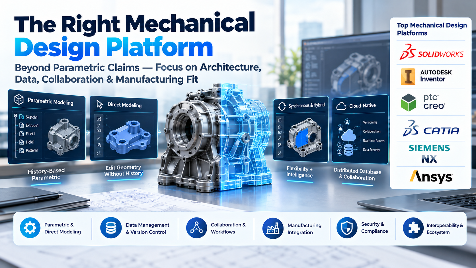
Mechanical design software anchors every physical product lifecycle, translating spatial concepts into manufacturable, inspectable engineering assets. Yet selecting a computer-aided design (CAD) platform frequently results in expensive mismatch. Engineering teams routinely buy enterprise-grade surface modelers when their actual operational bottleneck is distributed revision control, or they commit to nimble cloud solutions only to discover downstream machine shops cannot reliably parse proprietary assemblies without geometric translation artifacts.
Choosing the right mechanical design platform demands looking past vendor marketing claims regarding parametric modeling or generative optimization. The core decision hinges on architectural fit: how a platform structures its geometric modeling kernel, handles multi-part reference topologies, manages revision control across distributed engineering pipelines, and interoperates with manufacturing execution systems.
The Four Core Architectural Paradigms
Mechanical design tools are not interchangeable drafting boards; they are built upon fundamentally distinct mathematical engines and data architectures that dictate how parts can be created, altered, and collaborated on.
1. History-Based Parametric Modeling
History-based parametric design operates by recording geometric modifications sequentially in an ordered feature tree. Each sketch, extrusion, fillet, and hole depends mathematically on previously executed features and defined constraints such as dimensions, tangencies, and concentricities.
- Operational Reality: This remains the gold standard for high-precision, iterative mechanical engineering where functional relationships must remain deterministic. Altering a bolt-circle diameter updates corresponding clearance holes and mating flanges instantly.
- Failure Modes: The primary liability is parent-child failure. Modifying an early feature in a 2,000-step tree can silently corrupt downstream sketch references, causing assembly cascades to explode into dependency errors. Managing tree hygiene requires strict engineering protocols.
2. Direct Modeling
Direct modeling abstracts away the feature history. Engineers directly push, pull, rotate, and manipulate geometric faces and edges on the boundary representation (B-Rep) model, unencumbered by the original sequence of sketches.
- Operational Reality: Exceptional for early-stage concept development, mold-die repair, and preparing imported CAD files for computational simulation (FEA/CFD) where small fillets and engraving details must be removed without reverse-engineering a foreign feature tree.
- Failure Modes: Maintaining strict dimensional intent across complex families of interchangeable components is difficult, as geometric relationships are not enforced by persistent parametric rules.
3. Synchronous and Hybrid Engines
Hybrid approaches attempt to merge both worlds by running direct modeling operations while retaining or recognizing parametric intelligence on the fly. The modeling engine uses live rules to infer design intent—such as symmetry, parallelism, or coplanarity—across model faces during direct manipulation, whether the geometry was natively drawn or imported via intermediate neutral formats.
4. Cloud-Native Distributed Database Architectures
Traditional CAD saves designs as granular operating-system files (.prt, .sldasm, .iam). A modern cloud-native architecture replaces local files with a distributed cloud database engine where geometry, metadata, and history are stored as immutable transaction records.
- Operational Reality: Eliminates file-locking mechanisms, broken reference links when files are renamed or moved, and manual check-in/check-out procedures. Multiple engineers can concurrently work inside the same assembly structure in real time.
- Failure Modes: Teams working under strict sovereign data mandates or defense air-gapped security configurations frequently face severe compliance barriers when deploying pure multi-tenant cloud solutions.
Primary Mechanical Design Platforms Compared
The software landscape spans lightweight conceptualizers, industry-standard parametric platforms, and deep enterprise systems deeply tied to Product Lifecycle Management (PLM) backbones.
| Platform | Primary Operating Domain | Core Modeling Kernel | Deployment Model | Critical Operational Advantage | Core Operational Trade-Off |
| SolidWorks | Industrial equipment, consumer electronics, broad fabrication | Parasolid | Desktop-centric (Windows), optional cloud data connector | Pervasive supply chain ubiquity; massive third-party ecosystem | Fragile large-assembly performance without meticulous reference scoping |
| Autodesk Inventor | Heavy industrial machinery, automated production lines, tooling | ShapeManager | Desktop native (Windows), ecosystem integration | Native deep coordination with AutoCAD drawing standards and factory layout workflows | Historically siloed data management unless paired with dedicated Vault infrastructure |
| PTC Creo | Complex surface assemblies, powertrain design, industrial mechanisms | Granite | Desktop-centric, managed server architecture | Parametric stability across massive enterprise assemblies; complex behavioral modeling | Steepest operational learning curve; rigid interface paradigm |
| PTC Onshape | Agile product teams, distributed design reviews, multi-user mechanisms | Proprietary cloud engine | 100% browser-based SaaS | Zero workstation installation; integrated real-time multi-branch data management | Dependent on continuous broadband; limited offline contingency |
| Siemens NX | Aerospace, automotive structures, mission-critical tool and die | Parasolid | Desktop native (Windows/Linux), hybrid private cloud | Elite Class-A surfacing; seamless tight integration with multi-axis CAM | Substantial licensing overhead; significant administrative overhead |
| FreeCAD | Open-source research, custom scripting, independent prototyping | Open CASCADE Technology (OCCT) | Self-hosted desktop (Windows, macOS, Linux) | Free, completely modular Python API, no proprietary licensing or vendor lock-in | Inconsistent topological naming stability; fragmented interface conventions |
In-Depth Platform Analysis
SolidWorks: The Global Machine Shop Benchmark
SolidWorks remains the dominant common denominator across contract design agencies and industrial parts suppliers. When engineering teams need to hand off drawings, native parts, and assemblies to regional fabrication shops, the likelihood of that vendor operating a seat of SolidWorks approaches certainty.
Its strengths center on predictable workflows for sheet metal fabrication, standard structural weldments, tooling design, and the rapid generation of ANSI/ISO manufacturing drawings. Downstream machine shops can read and convert native configurations with zero geometry approximation.
However, SolidWorks runs on a single-core thread for core parametric rebuild operations, a constraint rooted in historical architecture. When assemblies swell past several thousand individual bodies or complex in-context sketch references, system latency spikes dramatically unless strict assembly management protocols—such as Large Assembly Settings, lightweight components, and speedpak configurations—are systematically enforced across the entire drafting department.
Autodesk Inventor: The Factory and Production Line Workhorse
Autodesk Inventor occupies a robust position among industrial machine builders and automation system integrators. It excels in contexts where custom machinery must interface directly with factory floor architecture, architectural drawings, and established civil layouts.
Inventor provides exceptionally deep rule-based automation via iLogic, allowing teams to embed conditional programming logic directly into assemblies. A sales engineer can update three capacity parameters, and Inventor will regenerate the internal drive-train geometry, recalculate structural frame sizing, and produce an exportable Bill of Materials (BOM) without manual CAD interventions.
Its operational challenge lies in collaboration across distributed teams. Unless supported by a properly deployed and maintained Autodesk Vault server infrastructure, handling file configurations, revisions, and release approvals across multiple geographic offices quickly manifests synchronization conflicts and fractured drawing links.
PTC Creo: Enterprise-Grade Parametric Rigidity
PTC Creo (historically Pro/ENGINEER) remains the platform of choice when mathematical accuracy and failure-proof parametric inheritance are mandatory. It is widely adopted across powertrain manufacturing, aerospace structural interfaces, and medical device enclosures.
Creo’s internal modeling kernel enforces structural discipline. Where more forgiving tools let an engineer construct under-constrained sketches or sloppy alignment references that break months later, Creo requires explicit parametric intent. This makes initial modeling feel slower, but enterprise designs built inside Creo exhibit unmatched resilience during sweeping engineering change orders (ECOs).
The trade-off is an interface that remains technical and unforgiving. Onboarding junior engineers or industrial designers accustomed to intuitive drag-and-drop mechanics requires dedicated training, and enterprise deployment demands robust PTC Windchill integration to unlock its configuration management strengths.
PTC Onshape: Cloud-Native Collaborative Engineering
Onshape re-engineers mechanical design around cloud database architecture rather than local binary files. Developed by early architects of the parametric CAD industry, it functions entirely inside modern WebGL-compliant web browsers without client-side installations.
Its competitive edge is frictionless data integrity. Because designs do not exist as loose files on a network drive, there are no file-locking errors, out-of-sync shared folders, or overwrites. Multiple mechanical engineers can design components concurrently within the same Part Studio while looking at the exact same live geometry. Its native version control system allows engineers to branch a design, test alternative load paths, and merge preferred geometry back into the primary release branch—bringing Git-style source control directly to mechanical hardware.
The operational limitation is institutional: organizations bound by rigid IT firewalls, sovereign air-gapped facilities, or defense-grade data hosting covenants often encounter compliance hurdles when evaluating multitenant software-as-a-service architectures.
Siemens NX: High-Volume Industrial and Surface Supremacy
Siemens NX operates at the absolute apex of the mechanical software hierarchy alongside Dassault Systèmes CATIA. It dominates the automotive, defense, and aerospace sectors where extreme computational throughput, Class-A aesthetic surfacing, and continuous multi-axis machining toolpaths intersect.
NX handles massive, complex assemblies—containing tens of thousands of complex components, like complete aircraft fuselages or internal combustion engines—with exceptional stability. Because Siemens develops the underlying Parasolid geometric kernel utilized by many of its competitors, its own native implementation features unparalleled mathematical fidelity and robust direct-editing capabilities.
The entry barrier is high. Licensing costs, administrative maintenance, and the required integration with enterprise PLM platforms like Siemens Teamcenter place NX out of reach for typical small-to-medium businesses or rapid-prototyping hardware startups.
FreeCAD: Modular Open-Source Autonomy
FreeCAD is a completely open-source, extensible parametric modeler built upon the Open CASCADE Technology (OCCT) geometric kernel. It runs natively across Linux, macOS, and Windows environments, making it a critical asset for academic research institutions, open-hardware initiatives, and privacy-conscious organizations.
The system is fully modular; the entire interface and underlying computation engine expose their capabilities via a native Python API. Engineers can script complex parametric sweeps, automate stress analysis pipelines, and program custom UI workbenches for specialized manufacturing tasks.
Its primary limitation is the topological naming problem—a persistent architectural challenge where modifying an internal sketch step can cause internal face and edge IDs to shuffle, inadvertently breaking downstream references. While active community development continues to stabilize these constraints, FreeCAD requires careful manual structure to match the production resilience of mature commercial suites.
Evaluating Total Cost of Ownership
Software acquisition costs represent only a portion of the total financial footprint of a mechanical CAD implementation. Operational overhead accumulates across several functional areas:
- Base License and Maintenance (15%): The direct upfront seat acquisition, annual maintenance contracts, or ongoing SaaS subscription tiers.
- Specialized Hardware (25%): Workstation-class engineering laptops equipped with dedicated CAD-certified graphics processing units (GPUs), high single-core processor speeds for parametric rebuilds, and substantial ECC RAM allocations to render complex assemblies.
- PDM/PLM Administrative Infrastructure (35%): The ongoing burden of managing on-premises Product Data Management servers, off-site replication, backup storage, access governance, and periodic client-server upgrade synchronization.
- Supply Chain Interoperability and Translation (25%): Labor spent converting files into neutral formats (STEP, IGES, Parasolid), fixing translation artifacts, re-applying lost dimensioning/tolerancing schemes (GD&T), and managing duplicated models across vendors.
Practical Selection Criteria
Selecting an appropriate CAD platform requires balancing engineering team size, product complexity, and supply chain demands:
- Massive Assembly Scale and Complex Surfacing: When designs routinely exceed 10,000 unique components or demand Class-A curvature continuity (aerospace fuselages, automotive exteriors), choose Siemens NX or CATIA paired with dedicated PLM backbones.
- Distributed Collaborative Engineering: When multi-site teams must work concurrently on interconnected assemblies without file-locking bottlenecks, choose PTC Onshape, provided external data hosting policies allow multitenant SaaS.
- Regulated Defense and High-Discipline Parametrics: When designs require rigorous revision stability within sovereign, air-gapped server environments, deploy PTC Creo with Windchill or SolidWorks with localized PDM.
- Factory Integration and Machine Automation: When custom automated equipment must route directly into facility floor plans, civil layouts, and architectural drawings, Autodesk Inventor offers the cleanest cross-discipline pipeline.
- Broad Supply Chain Ubiquity: When the highest operational priority is seamless part handoffs and drawing exchange with local contract machine shops, sheet-metal fabricators, and tooling suppliers, SolidWorks remains the default market choice.
- Programmatic and Cost-Constrained Modeling: For academic labs, embedded open-source projects, or specialized workflows requiring deep Python-driven automation without licensing overhead, FreeCAD provides full autonomy.
Strategic Implementation Takeaway
Do not purchase mechanical CAD software based on a vendor’s demonstration of edge-case capabilities like automatic generative lattice optimization or artificial intelligence sketching.
Instead, construct a focused pilot test around your team’s most vulnerable engineering workflow: build a realistic sub-assembly, execute a sweeping design modification that alters upstream reference geometry, release a drawing pack with standard Geometric Dimensioning and Tolerancing (GD&T), and export production-ready files to your contract manufacturer. The platform that handles that end-to-end iteration with the least geometric breakage, zero file synchronization errors, and clear revision clarity is the platform that will protect your hardware delivery timeline.
