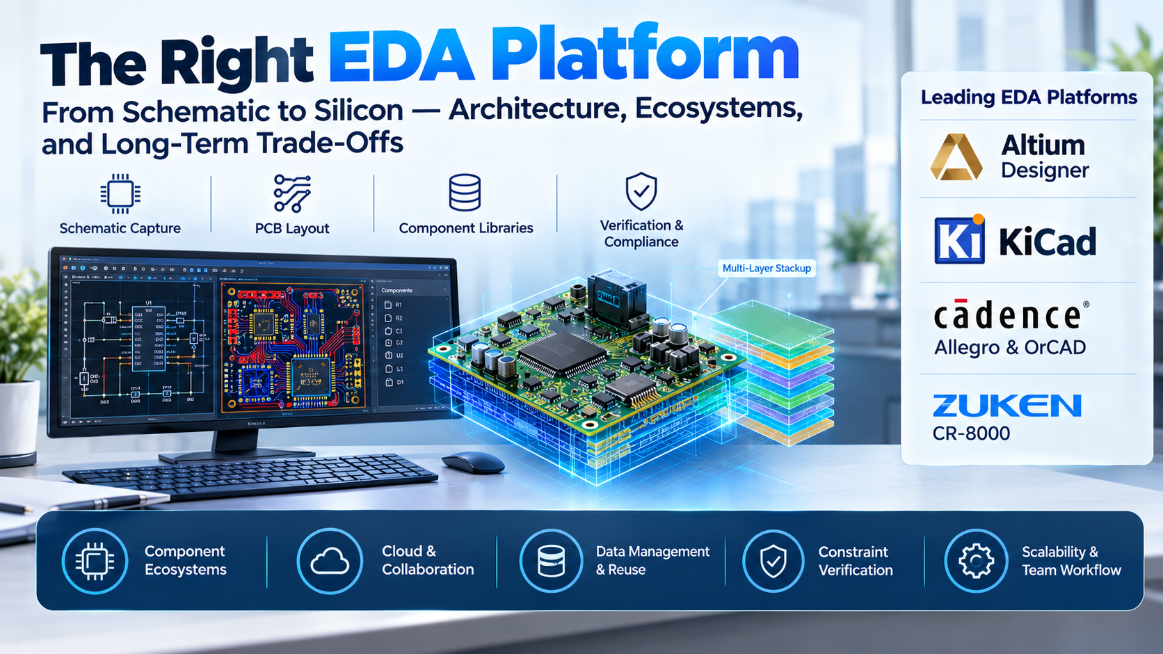
Designing a printed circuit board is fundamentally an exercise in risk management. At low signal frequencies and low layer counts, electronic design automation (EDA) software behaves like specialized vector drafting. As edge rates accelerate, layer stacks deepen, and components shrink to sub-millimeter pitches, the board transitions from an interconnect map to a complex distributed-element electromagnetic environment. At that threshold, a software platform’s routing intelligence, constraint verification, and manufacturing output integrity dictate whether a prototype functions on initial power-up or becomes an expensive fabrication failure.
Choosing an EDA platform is rarely just about drafting traces. It binds an engineering team to a component library ecosystem, a specific mechanical integration model, and a data management pipeline. Selecting the wrong platform creates long-term friction: small teams get crushed by the administrative overhead of enterprise tools, while growing teams hit hard walls when low-end tools fail to resolve high-speed constraints or multi-board system relationships.
The Four Core Architectural Models
EDA software divides along distinct architectural fault lines. These determine how the software handles component data, manages routing mathematics, and scales across design teams.
1. Integrated Desktop Suites with Relational Databases
These systems link a schematic capture engine, a PCB layout workspace, and a component database inside a unified desktop environment. Changes move bi-directionally between schematic and layout via forward and back-annotation operations.
- Operational Reality: The primary workhorse of commercial hardware development. Highly responsive graphics rendering, robust multi-monitor layouts, and deep local control over design files.
- Failure Modes: File synchronization risks emerge quickly when multiple engineers touch the same board or libraries without dedicated, external Product Data Management (PDM) software.
2. Enterprise Unified-Data Environments
Enterprise platforms separate drafting clients from the underlying database, housing libraries, rules, and designs within centralized servers. Design reuse occurs through verified functional blocks rather than simple copy-pasting.
- Operational Reality: Tailored for complex systems where a power supply or high-speed memory interface must be designed once, mathematically validated, and consumed across dozens of distinct products.
- Failure Modes: Severe implementation and administrative burdens. Modifying a component footprint often requires administrative approval workflows, slowing early-stage, agile prototyping.
3. Native Browser-Based and Cloud EDA
These engines execute layout calculations and data synchronization on remote cloud infrastructure, serving the interface to local clients via WebGL and browser environments.
- Operational Reality: Eliminates installation bottlenecks, local library sync errors, and license-server management. Design reviews function through real-time commenting and shared URLs, mirroring cloud productivity suites.
- Failure Modes: Heavy computational dependencies on continuous broadband access. Complex multi-layer boards with extensive copper pours can encounter browser memory caps, and defense or healthcare sectors often face regulatory obstacles hosting design IP on public multitenant clouds.
4. File-Centric Open-Source Stacks
Independent modular executables share project states using human-readable, plain-text configuration and layout files.
- Operational Reality: Complete user control over design assets, free of licensing servers, subscription expirations, or proprietary lock-in. Ideal for integration with text-based version control tools like Git.
- Failure Modes: The user is entirely responsible for library curation, mechanical clearance checking, and assembly rule validation. Turnkey enterprise features, like automated constraint management, must often be substituted with third-party scripts or manual calculations.
Primary PCB Design Platforms Compared
Selecting a tool requires matching design complexity, organizational scale, and compliance mandates against specific platform strengths.
| Platform | Primary Operating Domain | System Architecture | Licensing Model | Critical Operational Advantage | Core Operational Trade-Off |
| Altium Designer | Mid-to-high complexity commercial electronics, IoT, industrial products | Desktop (Windows) with native cloud collaboration | Annual subscription or term-based licensing | Unified ecosystem linking schematic, layout, 3D clearance, and component supply tracking | Heavy memory demands on large boards; frequent update cycles alter interface behaviors |
| KiCad | Open-source research, small-team engineering, rapid prototyping | Desktop (Cross-platform: Linux, macOS, Windows) | Open-source (GPLv3) | Free of licensing overhead; human-readable files integrate natively with Git workflows | Manual library validation; lacks native high-level simulation tools for advanced signal integrity |
| Cadence Allegro & OrCAD | High-speed computing, automotive, defense, high-density interconnect (HDI) | Enterprise client-server (Windows/Linux) | Tiered perpetual or term enterprise licenses | Unequaled constraint management and automated high-speed routing engines | Steep learning curve; modular licensing increases cost per seat significantly |
| Siemens Xpedition & PADS Professional | Large enterprise systems, complex wire-harness integration, multi-board aerospace | Enterprise client-server (Windows) | Enterprise corporate contracts | Concurrent multi-user routing; deep integration with Siemens mechanical and PLM stacks | Massive administrative footprint; excessive complexity for small, agile hardware teams |
| Autodesk Fusion Electronics | Mechatronic assemblies, consumer gadgets, compact electromechanical packaging | Hybrid desktop client with cloud backend (Windows/macOS) | Bundled software subscription | Bi-directional native synchronization between parametric CAD bodies and electronic traces | Layout engine lacks depth for high-speed length matching and dense multi-layer HDI |
Detailed Platform Analysis
Altium Designer: The Commercial Standard for Mid-Tier Hardware
Altium Designer dominates the commercial hardware development space, particularly among venture-backed startups, mid-sized original design manufacturers (ODMs), and industrial electronics firms. Its enduring strength is structural cohesion: schematic capture, 2D layout, real-time 3D clearance checking, and supply-chain inventory visibility operate inside a single, intuitive interface.
Its 3D clearance engine reads native mechanical models directly from STEP and Parasolid formats, alerting engineers to collisions between tall electrolytic capacitors and enclosure walls before ordering bare boards. Integrated data links directly connect to major electronic component distributors, tracking unit costs, stock counts, and lifecycle statuses during the schematic phase.
However, Altium’s feature-rich interface carries operational costs. The software relies heavily on high-end graphics processing and system memory. Furthermore, while its integrated cloud collaboration platform simplifies sharing, it can present governance and data-sovereignty hurdles for defense contractors operating under strict export control mandates unless expensive private-server setups are purchased.
KiCad: Open-Source Autonomy and Unencumbered Workflow
KiCad has evolved from a hobbyist alternative into a capable suite for professional engineering teams, driven by an active open-source core team and institutional contributions from research facilities like CERN.
Because its project assets—including schematics, board outlines, and footprint libraries—are saved in UTF-8 plain text using S-expressions, KiCad integrates with software engineering pipelines. Teams can commit board designs directly to standard Git repositories, conduct meaningful diffs between schematic revisions, and integrate automated continuous integration (CI) actions that render manufacturing archives on push.
The tool provides capable push-and-shove trace routing, interactive length-tuning for differential pairs, and flexible layout tools. Its primary operational limitation is accountability: there is no vendor support desk to resolve obscure routing engine anomalies. High-reliability applications also require independent verification, as its component libraries are largely community-maintained and must be audited manually for manufacturing accuracy.
Cadence Allegro and OrCAD: High-Speed and HDI Dominance
When a board includes multi-gigabit interfaces, high-pin-count Ball Grid Arrays (BGAs), and tight High-Density Interconnect (HDI) structures with blind and buried microvias, Cadence Allegro and its sibling platform, OrCAD, remain the definitive choice. The platform powers major computing platforms, networking backplanes, and high-reliability automotive controllers.
The defining differentiator is the Cadence Constraint Manager. Rather than treating rules as simple minimum and maximum clearance limits, Cadence provides a unified tabular database where engineers define intricate physical, electrical, and timing parameters. Skew matching across multi-lane differential buses, phase tolerances, impedance profiles, and return-path clearances are validated on the fly as traces are drawn.
The barrier to entry is substantial. Cadence tools require dedicated training, have complex, multi-tiered licensing menus, and use an interface that prioritizes rigorous execution over modern consumer aesthetics. Deploying Allegro without an experienced CAD administrator often leads to project delays during initial workspace configuration.
Siemens Xpedition and PADS Professional: Enterprise Systems
Siemens approaches electronics from a complete systems perspective. Within large industrial corporations, an electronic circuit board cannot exist in isolation; it sits inside a complex web of structural sheet metal, inter-chassis wire harnesses, and enterprise supply chains.
Siemens Xpedition provides true multi-user concurrent layout. Multiple PCB designers can work inside the exact same physical board file simultaneously, routing distinct functional areas while the engine arbitrates space and boundary collisions in real time. Coupled with PADS Professional for smaller, agile departments, the platform provides clean pathways into Siemens Teamcenter for enterprise-wide Product Lifecycle Management.
This operational scale makes Siemens platforms excessive for small design houses. Building the necessary part databases, signal simulation models, and design reuse libraries requires significant labor before the first trace is placed.
Autodesk Fusion Electronics: Unified Electromechanical Development
Autodesk integrated the legacy EAGLE routing engine directly into the Fusion parametric CAD environment, addressing the persistent rift between electrical and mechanical engineers.
In traditional development, exchanging geometric modifications between electrical layout and mechanical housing involves exporting intermediate files back and forth, frequently resulting in lost metadata or unmapped spatial updates. Fusion resolves this by sharing a single data model. If an industrial designer moves a mounting standoff or shifts a USB-C connector on the outer casing, that modification reflects directly inside the electronic layout view without file translation.
While this makes the platform well-suited for consumer enclosures, IoT wearables, and tight mechatronic packages, its routing tools become restrictive on complex, multi-layer designs. It lacks the advanced routing acceleration, rigorous high-speed constraint automation, and specialized layer-stackup control found in dedicated EDA platforms.
Evaluating the Hidden Costs of EDA Adoption
A seat’s advertised purchase or subscription price accounts for only a fraction of its true organizational cost. When evaluating platforms, calculate the long-term operational liabilities:
- Library Maintenance and Auditing: An engineering team spends significant time building and maintaining components: schematic symbols, layout footprints, 3D step models, and thermal land parameters. Moving to a new platform often renders existing libraries unusable without manual translation and re-auditing. A single incorrect footprint pinout can render an entire fabrication batch scrap.
- Supply Chain Interoperability: If contract electronics manufacturers (CEMs) or assembly houses receive design files in an unfamiliar format, delays occur. While standard Gerber (RS-274X) files are widely accepted, modern intelligent manufacturing handoffs rely on ODB++ or IPC-2581. These formats bundle netlists, component placement coordinates, and Bill of Materials metadata directly into the design file, eliminating manual translation steps at the assembly plant.
- Onboarding Friction and Architectural Discipline: Transitioning an engineering group from a permissive, freeform layout platform to a strict constraint-driven enterprise tool can temporarily lower productivity. If the team lacks dedicated administrative support to configure rules, templates, and libraries, they will either bypass the system’s protections or experience delays on initial release deadlines.
Practical Selection Guidelines
Selecting the right EDA environment comes down to matching your operational needs with the platform’s architectural strengths:
- For Agile Startups, Industrial Equipment, and IoT: If your products are moderately complex (4 to 12 layers, standard DDR interfaces, mixed-signal routing) and your team must move quickly between design, mechanical validation, and supply-chain procurement, Altium Designer offers the most complete out-of-the-box workflow.
- For High-Speed Computing, Telecom, and Dense HDI: If you are building motherboards, complex switchgear, or multi-core processor platforms with multi-gigabit differential signaling and high-density pinouts, Cadence Allegro’s Constraint Manager and signal-integrity automation justify its operational complexity.
- For Cost-Sensitive Teams, Open Hardware, and Git Workflows: If you want zero licensing overhead, prioritize long-term asset control, or rely on distributed contributors using automated version control pipelines, KiCad is a reliable, enterprise-capable solution.
- For Large-Scale Enterprise Aerospace and Automotive: If your design teams span hundreds of engineers across multiple countries needing concurrent multi-user layout access and deep PLM integration, Siemens Xpedition provides the necessary systemic guardrails.
- For Enclosure-Constrained Consumer Products: If your board’s geometry is dictated entirely by unique, ergonomic physical casings and mechanical assemblies, Autodesk Fusion Electronics eliminates translation friction between mechanical CAD and PCB routing.
Strategic Implementation Takeaway
Do not select an EDA suite based solely on a vendor’s demonstration of automated auto-routing or cutting-edge features. Auto-routers are routinely bypassed by senior PCB layout engineers in favor of manual, controlled trace topologies.
Instead, build your evaluation around your team’s most time-consuming real-world bottlenecks: How quickly can a junior engineer construct a reliable, zero-defect component footprint? How cleanly does the system map thermal vias and impedance rules? How much manual cleanup is required to generate reliable ODB++ and pick-and-place files for your manufacturing partner? The platform that streamlines those everyday tasks with the fewest workarounds is the tool that will keep your hardware shipments on schedule.
